Solving the Raspberry Pi Reboot Problem
The problem
Many people have sought to build portable devices based on the Raspberry Pi. Typically, they use a USB powerbank to power the Pi and its accessories. However, they commonly discover that the Pi reboots when the powerbank is plugged in for charging or unplugged for portability.
Most USB powerbanks stop providing power momentarily when their charging circuits are turned on or off. This causes the Pi to reboot, which isn't nice.
This problem has been discussed extensively (links: 1, 2, 3).
Have a question? Want to contribute? Try the "Other Projects" section of the Raspberry Pi forum. Start your title with "WBC".
Previous attempts
Previous searches for solutions have led to recommendations that people buy specific powerbanks. The Voltaic V50 has been recommended as a USB UPS. The ZMI Ambi 1000 has also been recommended, as have the Anker Astro Mini (3200 mAh), the RS Pro 5000 mAh, and the Zendure A3.
Unfortunately, limiting yourself to a specific UPS brings supply problems (is it still available? has the manufacturer changed the design without changing the model number?). It also limits your ability to meet other specifications; the powerbank that doesn't cause reboots might not be the right shape or size for your design.
The need for uninterrupted portable power has also led to the development of custom devices designed to avoid power interruption on the Raspberry Pi. These devices also tend to manage shutdown. They include the Juice4Halt, the device from Raspberry PiQ, the PiUPS, and the UPS Pico. Unfortunately, these devices are too complex for a system builder to assemble independently and are available from just a few sources (back to the supply problem noted with the "specific powerbank" solution). In addition, most of them block the GPIO ports, rendering them unavailable for other uses, and increase the minimum thickness of the resulting portable device.
I would love for someone to start building anti-interruption devices that are mechanically flexible and attach via USB instead of the GPIO ports. These might be used with any computing module, not occupy the GPIO ports, and not increase the minimum thickness of the Pi-based device. But, I digress.
WARNING: Any use of high-capacity capacitors is dangerous, especially since you cannot see whether they are charged. You may shock yourself or kill your Raspberry Pi or other devices.
The solution: Short version
First, make sure that your powerbank delivers at least 4.7V both when charging and when not charging. You can determine this using a USB multimeter. If your powerbank does not meet this standard, get another one.
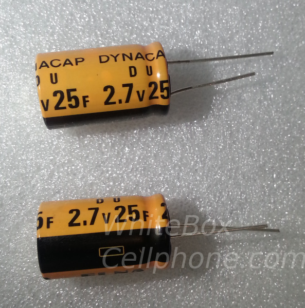
Second, get some supercapacitors between 10F and 25F. Typically, these have maximum voltages of 5.5V or 3V.
Third, identify how the capacitors will be connected. You can connect the capacitors to the GPIO header pins 2 (positive) and 6 (negative), as well as 4 (positive) and 14 (negative) using Dupont wires. If you have 3V capacitors, you will have to attach them to each other in series before attaching them to the Pi.
 Two 25F capacitors |
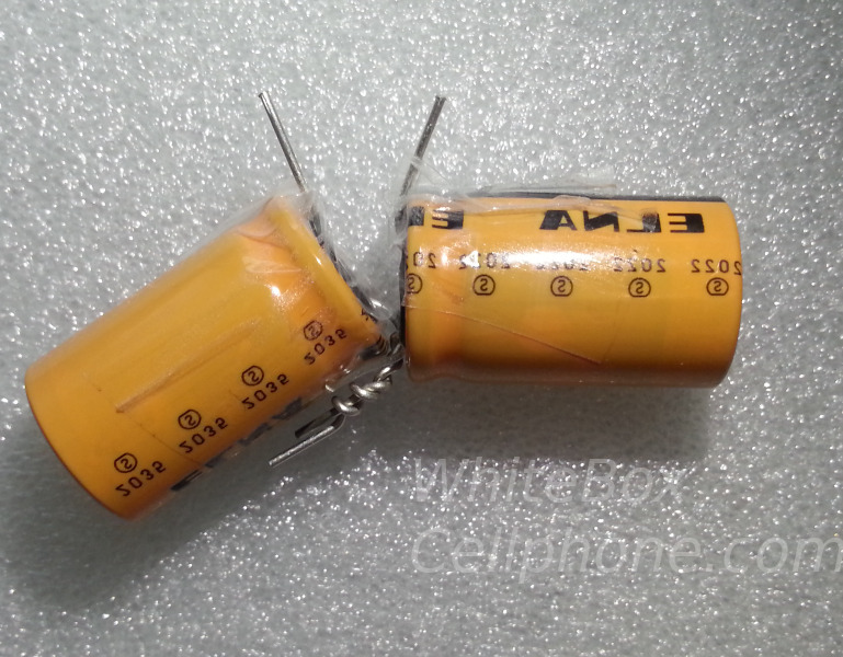 The negative contact from one capacitor is tied to the positive from the other to put them in series. Plastic tape is used to prevent shorts. |
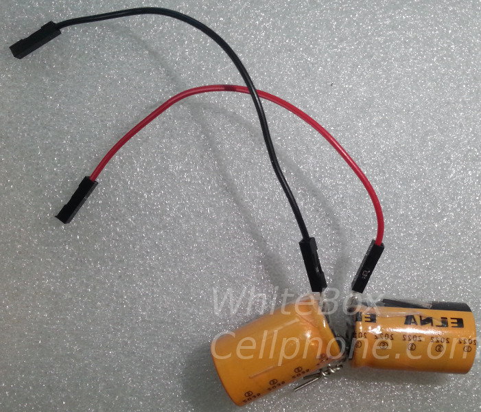 Dupont wires are attached to connect the capacitors to the Raspberry Pi. Please read the full instructions. |
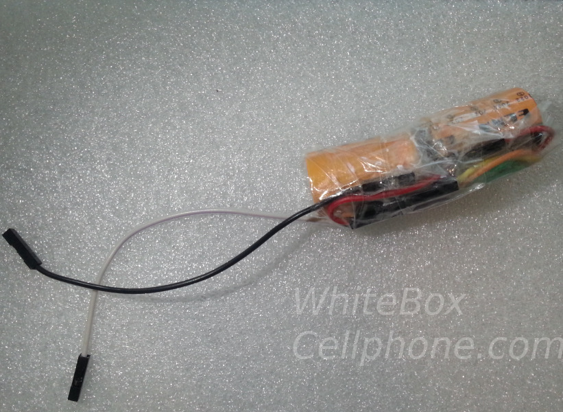 The wires are bound with tape to prevent movement. |
Fourth, determine how many Dupont wires to use. Attach several (perhaps 6 or 7) Dupont wires in series with the capacitors and link the capacitors to Pi GPIO pins 2 (positive) and 6 (negative). Plug the powerbank in to the Pi. If the Pi boots, carefully discharge the capacitors fully (you can run them across a 100 ohm resistor).
Remove a Dupont wire, attach to the Pi, and plug in the powerbank to boot.
Here is where you risk your powerbank. You need to repeat the above process, removing one Dupont wire each time, until the powerbank refuses to power the Pi. Most powerbanks will switch off when the current requested is too high, but some may permanently self destruct.
Powerbanks are cheap. Buy two.
Fifth, test the system. Once you know the minimum number of Dupont wires that will allow your powerbank to supply the Pi, attach the lines to the Pi. Boot from the powerbank, allow the capacitors 120 seconds to charge, and try plugging the powerbank into a wall charger.
If the device stays on, great! If not, either add more capacitors or remove accessories from the Pi (more accessories = more current required = larger capacitance requirement).
Sixth, wrap the capacitor(s) and wires tightly with tape and place them in your system permanently.
The solution: Detailed explanation
My solution is to use a few supercapacitors attached to the Raspberry Pi 4 GPIO ports (but not occupying all of them) to power the Pi momentarily when power is lost.
No one supercapacitor size fits all situations. Before starting, you must understand how supercapacitors work and the factors that constrain your operating window. You absolutely must have a USB power meter (something that tells you the actual voltage and current transferred across a USB cable). First, the factors that we will consider:
- V1: The voltage provided by your powerbank when not charging
- V2: The voltage provided by your powerbank when charging
- i: The current required by your device
- I: The maximum current that your powerbank can deliver to your device
However, not all of the charge stored in the capacitor is available to your device. Only the charge stored at a voltage larger than the minimum device operating voltage (Vmin) can be used. We don't know what Vmin is, but lets estimate it to be 4.2V. Charge will be stored up to the voltage that the device operates on. Some powerbanks provide a lower voltage when charging than when not charging. Lets set Vpowerbank to the lower of V1 and V2.
If we consider an imaginary system with a 10F supercapactor, Vmin of 4.2 V, and Vpowerbank of 4.8 V, we find that a device that uses 1 A of current could be powered for 6 seconds. Of course, real life isn't so simple because the current is not constant and there is resistance in the system. Lets rewrite our equation to account for resistance (R).
So, the 6 seconds that we estimated earlier for our imaginary system is reduced by an unknown resistance. We can't measure this resistance without some fancy tools, but we know that it is there.
In addition to considering the capacitor discharge process (when the capacitors) deliver energy to the device), we have to consider capacitor charging. I won't show the equations here since we can't measure anything related to them, but capacitors charge very quickly when they are empty. If the capacitors in your system are too large, the current that they demand when charging can cause your powerbank to stop delivering power or even die permanently. We are going to define idemand as the current that the capacitor would demand over the initial first fraction of a second if only the resistance within the Raspberry Pi system were present (Rpi). We define ipowerbank-max as the maximum current that your powerbank can deliver for a fraction of a second.
Now, lets talk about attaching the capacitors to the Raspberry Pi. Although they are mechanically unreliable, Dupont wires can be used to attach capacitors to the Raspberry Pi GPIO header. The positive lines go on pins 2 and 4, while the negative lines go on pins 6 and 14 (you can use just 2 and 6 if you want to attach only one set of capacitors). Each Dupont wire has a resistance. They are probably mostly similar, though they aren't the same. For our purposes, we will assume that all Dupont wires have the same resistance Rdupont
When you get a set of Dupont wires, try to identify the ones that connect poorly. Attach each wire end to either a male wire or a GPIO pin. If it slides off too easily, throw it away. Work only with the wires that give some resistance when you try to pull them off.
Follow the instructions in the "short version" text above to find the minimum number of Dupont wires required and implement the system. If you can measure the resistance of your Dupont wires, you may be able to source an appropriate resistor and eliminate the extra wires from the system.
However, even without solving the equation, you can see how the capacitance, resistance (number of Dupont wires), and powerbank maximum current define the operating window for this system. It is possible to have a powerbank that is too weak or a Pi whose accessories make it impossible to protect. We can't measure Idemand, but we know that it is proportional to C, so we define a proportionality constant α such that Idemand=C×α. This leads us to a quadratic equation.
I leave solution of the quadratic as an exercise for the reader.